
Take two thin crystal sheets, turn one slightly and look at their overlap. A larger pattern can appear even if nothing inside either sheet moves. Sandholt, Gauquelin, Mangeri and their colleagues used a more demanding version of that experiment. They bonded two free-standing strontium titanate membranes closely enough that atoms near the join could rearrange. In the November 18 Nature paper, the researchers describe an orderly grid of line defects at that buried interface, with a related pattern in an electron microscopy signal. The finding turns the angle between the sheets into a way of changing the material at the join. That is a more interesting design possibility than a picture that only looks different when rotated. The paper in Nature
What matters next is what that deliberately formed boundary can do. The microscopy and calculations support a connection between the defect network and a pattern in the direction of local polarisation. The team also calculates electronic states concentrated near parts of the grid. The Technical University of Denmark puts the open question plainly. Further experiments are needed to find out whether the lines conduct electricity. No memory cell was demonstrated. The research is good reason to study an interface the researchers can tune, and a reason to demand a separate electrical measurement before assigning that interface a job in a device. DTU’s account of the experiment
An overlap can produce an image or change what is underneath it#
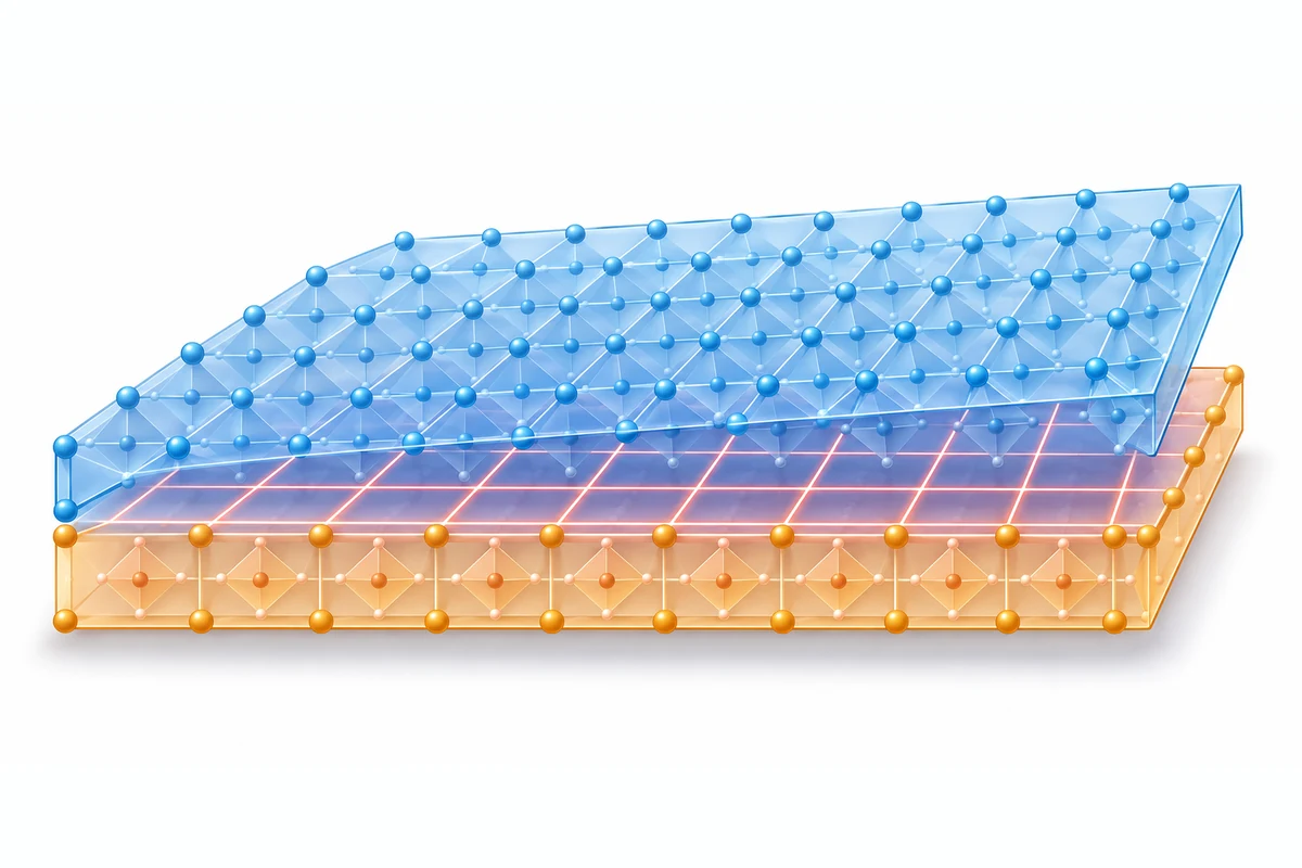
Look through two square meshes with one turned a few degrees and broad bands appear. Their spacing changes as one mesh turns. The small openings are where they were before. What is new is the pattern of coincidence between the two meshes. An atomic lattice can produce an analogous moiré pattern when it is overlaid on another lattice. That idea gives readers an intuitive first picture for the study. The picture alone leaves out the possibility that the parts at the join interact strongly enough to change their positions. The most important thing to know about the laboratory sample is that the two layers were able to do more than overlap.
The sheets are made of strontium titanate, usually written SrTiO₃, an oxide with a perovskite structure. DTU describes each membrane as about ten nanometres thick. That thickness is small enough to make handling and alignment consequential while still containing many layers of atoms. The term free-standing refers to the ability to release the crystal film from the surface on which it was originally grown. Researchers can then stack the components with a chosen relative orientation. The flexibility comes from being able to set the geometry of the pair and examine a boundary that would have been harder to create by simply growing a thick crystal in one piece.
The strong bonds between the two sheets create a competing demand. The two lattices do not align everywhere, while local arrangements of atoms can become more favorable where the sheets meet. Atoms near the boundary can shift to recover a favorable alignment over parts of the sample. The mismatch then builds up along narrow regions where the arrangement has to change. Those are dislocations, line defects in the crystal. The paper identifies a network of screw dislocations. Their orderly arrangement is the result of the interface relaxing into a different structure. A geometric pattern and a reconstructed network may both repeat, and an image at first glance might not tell a reader which one they are seeing.
The researchers had to find the boundary inside the image#
DTU describes a moment when the first microscopy images appeared to show the geometric pattern and gave little indication of the grid that calculations had suggested. In a transmission electron microscope, the electrons pass through one sheet, the boundary and the other sheet. The signal carries information from more than the small region of interest. If much of the visible contrast reflects the two layers together, identifying one kind of pattern in a projection will not settle which atomic arrangements exist at the join. The researchers needed to know what each possible structure would look like to the instrument before choosing a way to separate them.
The team simulated the passage of the electron beam and examined specimens cut in different directions. The cross-sections let the investigators look at features lying close to the interface. Researchers at the University of Antwerp and the UK’s SuperSTEM laboratory took part in the microscopy. A cross-section gives a different view from the projection through both layers, and the selection of its orientation matters for interpreting a spacing measured there. When a geometry predicted in a calculation appears where the model expects it in a different measurement, that gives the hypothesis a better chance to survive. The experiment was designed around what was difficult to see.
The chain of evidence has an important consequence for how the research should be explained. A photograph of two crossed meshes helps people imagine rotation. A drawing of a line net helps them imagine real distortions. Neither is a microscope measurement, and the microscope signal also needs interpretation. Putting the different views beside each other can make the work easier to follow. The first view says where two regular patterns would line up. The second identifies atomic positions that no longer match that rigid arrangement. The third captures a variation in the way the electron beam responds as it traverses the material. The value of the work lies partly in tying those views together without asking any one view to answer all the questions at once.
Twist angle gives a way to tune spacing within a measured range#
DTU reports that the team observed the dislocation network for sample angles of 5, 7.5 and 10 degrees. At 20 degrees the pronounced network seen in the lower-angle cases was absent. Extended Data Figure 4 in the Nature paper reports example spacings from cross-sections. At 7.5 degrees the observed spacing there was 2.1 plus or minus 0.2 nanometres. At 10 degrees it was 1.5 plus or minus 0.2 nanometres. These are measurements in the specified viewing geometry, with a relation to the spacing in the interface plane that the paper discusses. They describe one dimension of the defect network, separate from film thickness and the overall size of the assembled film.
That shrinking spacing is useful because the starting choice is macroscopic enough to specify during assembly. The outcome is a regular structure much smaller than the pieces being handled. The smaller angle leaves a longer distance between corresponding mismatches before the pattern repeats. A larger angle can produce a tighter spacing within the range where distinct dislocation lines are supported. When the rotated lattices move farther from alignment, there can come a point at which the same sharp network is no longer a good description. The 20-degree measurement is valuable for making the limit visible. It gives a reader a reason to speak of tuning within a range, with no promise that turning any two oxide membranes farther will produce ever smaller useful features.
The results make alignment, sample quality and definitions part of any next comparison. Measuring whether two groups made the same structure requires measurements of actual relative angle and spacing through a comparable geometry. A useful report would also show what happens across more than one part of the interface and in more than one prepared sample. A small difference between chosen and measured angle might be noticeable when the feature scale is nanometres. These details determine whether engineers eventually have a knob they can use with confidence or an effect that only appears in certain specimens. The study provides a direction for that comparison and real landmarks to start from.
Polarisation describes an arrangement of charge#
The electrical part of the study requires a second distinction. Polarisation concerns the orientation of a separation between positive and negative charge in a material. In a small region, different polarisation directions can be drawn as arrows. When the directions rotate around a point, researchers can describe a vortex, and a related arrangement with the opposite winding is called an antivortex. This is a way to describe the spatial arrangement of directions. The word vortex can suggest fluid flowing in a circle. Here the picture represents an organised texture in the material, and the arrow map by itself cannot give a measured electrical current.
The paper uses four-dimensional scanning transmission electron microscopy to map a beam deflection pattern that lines up with the dislocation network. At many positions of the scanning beam, the instrument can record a diffraction pattern rather than only a single brightness. From these data a researcher can examine how the passage of the electrons changes across the sample. The analysis of how those changes correspond to local polarisation uses modelling, as DTU’s explanation makes clear. That matters for a buried boundary where contributions to the measured signal can overlap. The strongest statement the result supports joins the measurements and the interpretation with their respective scope.
Another clue comes from deformation that varies from place to place. An uneven strain can create a polar response through flexoelectricity. Near the grid, the deformation can change rapidly across a small distance. Researchers used simulations of the atoms and a model describing how patterns of polarisation compete and settle in space. The result gave a physical explanation for why neighbouring areas could favour different directions and why the vortex and antivortex patterns align with the dislocation network. The useful research result is a link between where the atoms are displaced and where the polar texture is expected to form. Testing whether a particular electrical operation can change or read that texture is a separate experiment.
Computation helped choose a better experiment#
One of the most relevant uses of machine learning here happens before a public demonstration. The researchers trained an interatomic potential using quantum-mechanical reference calculations. The learned relationship lets them simulate the likely forces and movements of atoms across a larger system than the underlying reference calculation could conveniently cover. They used it to compare a pair of rigidly rotated layers with a structure that could relax and develop a network. That calculation gave the microscopy team a feature and a position to look for. An image would still have to settle whether the predicted structure existed in the actual material.
The same logic explains why sharing a model is useful and why it is only part of replication. The paper links to the simulation code and models and says supporting data can be requested from the authors. Another group can check whether the same model produces the same structure under similar conditions. Reproducing the material and microscopy also asks for comparable membranes, a controlled interface and equivalent analysis choices. Agreement between simulations and several views makes the explanation stronger because the researchers can look for the same pattern in ways with different limitations. It also makes disagreements more informative. A larger mismatch in a newly made sample could point to a different bonding condition, a wrong assumption in the model or a difference in the observation, and those are distinguishable follow-up questions. Simulation materials linked by the authors
This work fits in a longer investigation of twisted oxide membranes. A previous Nature study reported a ferroelectric vortex pattern using twisted barium titanate layers. It is a useful point of comparison because it shows why directional patterns are worth looking for when one crystalline film is rotated relative to another. The strontium titanate paper puts the burden of proof in a different place. Its proposed cause is a reconstructed interface, and the measured network has an associated spacing and geometry. Comparing the two results should account for the materials and the method used to identify the pattern. The comparison is most helpful when it shows what the new demonstration adds to the family of effects. Earlier work on barium titanate
A future device would need a dependable way to change and measure a state#
DTU names memory as one possible reason for being interested in a tunable grid. To make that connection concrete, a laboratory would first have to identify a state it can set, distinguish it from other states and retrieve it later. Polar textures can offer an interesting starting point for asking those questions. A regular pattern may provide many recurring sites to examine under the same conditions. The study has already shown a method to change the spacing through the twist of the sheets. It has not supplied a way to assign and reliably read a bit at each point. The density of a patterned material and the density of usable information are two different quantities that need separate tests.
The electronic calculations point to states near features of the network that differ from those away from it. A local change in the available electronic states can be a reason to look for unusual conductivity or another response. Whether charge can move along a line depends on how the states connect, how the interface is contacted and the conditions of the measurement. DTU explicitly leaves conduction open. It would be informative to compare points at intersections, points along lines and points well away from them, recording the expected contrast before looking at the result. If a response appeared, dependable controls would still be needed to separate the boundary from the rest of the stack.
Practical memory would ask more of that response. A test would need to measure whether a chosen state lasts, how reliably it can be written and read, how often it can be repeated, what temperature range it tolerates and what resources are needed to address it. An interface pattern can be scientifically useful without meeting those tests. For a materials researcher, even an experiment that rules out useful conduction can explain how the crystal and its electronic structure are related. For someone tracking technology close to deployment, a working small device with repeated measurements and stated conditions would be the next evidence that matters.
The way the sheets bond is a second experimental variable#
The angle is easy to identify, yet the event involves two choices that deserve to be kept together. The first is how far one layer is turned. The second is the quality and nature of the interface that forms when the sheets are brought together. Two samples at the same measured angle could have different local bonding, or different opportunities for atoms to rearrange at the boundary. That would change the physical question being asked. Turning the sheet lets researchers select a geometric input. The result depends on what the material does with that input. Future comparisons would benefit from describing both the orientation and the condition of the join rather than reporting only the angle on the sample label.
Changing the material would be an equally informative test. A different oxide can have a different lattice, stiffness, or electrical response to the strain around a defect. A study might find a related set of lines with little detectable polar response. It might also find a similar polar pattern with a change in the angle range where the grid stays distinct. These are separate possible observations. Finding the same effect across a family would make it easier to identify which properties are essential. Finding the pattern only in a narrow class would give designers a more precise guide to where to look. The usefulness of the present experiment is that it offers measured features against which such comparisons can be made.
How to judge an attempted repeat depends on the result of interest. A group testing the structure can ask whether the positions of the defect lines agree with those it expected to find and whether the spacing follows the same relation to angle. A group testing the polar response can ask how much the signal survives slight differences in the way the samples are prepared and observed. Any interpretation of electronic transport would need its own baseline and measured current. This separation helps make a negative outcome useful. It would be possible for the structural prediction to hold while a planned electrical use proves impractical. That would still identify an interface worth studying and tell another group where the evidence stops.
There is a historical reason to value a defect that can be created in this way. Crystal defects have long mattered because a small interruption in atomic order can change the properties of a much larger material. In fabrication they can be a source of variation, so much of the practical work goes into deciding which ones to suppress and which ones to make repeatable. A regular grid offers a different kind of opportunity from a randomly placed line. One experiment can sample similar features at several locations and examine what changes between a line, an intersection and the relatively undisturbed region. A controllable defect becomes a subject for engineering once these comparisons consistently identify a response of interest.
Repeatability is the bridge between a chosen angle and a useful material#
The sharp line grid is appealing because of its order. Order also gives the investigators a standard for recognising when a new sample behaved differently. A persuasive follow-up would compare multiple membranes at each target angle and make clear where the structure was uniform or interrupted. It would be useful to see how performance changes with thickness, preparation and the quality of the interface. There is also a larger-area question. A grid visible in a small field of view says something valuable about a local sample, while a device platform would need evidence about variation over the area it intends to use. Matching the measurement to the claim is the best way to recognise progress.
The next study could divide its questions by what it can measure. A structural result could establish that the observed spacing can be reproduced. A polar measurement with a separate control could test whether the predicted charge arrangement follows the same pattern in a second preparation. An electrical experiment could determine whether the boundaries carry charge differently from nearby regions and under what conditions. Those outcomes may agree or diverge. Each combination would sharpen the explanation and indicate where a future device experiment should begin. This is an advantage of a tunable structure. It lets researchers vary a known geometrical input and ask which resulting properties really follow it.
The present result gives an old idea about defects another use. A line where a crystal breaks from regular order can correspond to a reproducible structure with an electrical signature worth investigating. This group showed how to create the array by twisting two bonded sheets and how to find it at a boundary that ordinary images could obscure. The work earns attention for adding a way to research local behaviour in oxide materials. It will earn a place in device design when a subsequent experiment connects that tunable boundary to measured electrical work with convincing controls. The small grid is already real. Its job remains a good research question.